


Vehicle Localization using 76GHz Omnidirectional Millimeter-Wave Radar for Winter Automated Driving.pdf
50墨值下载
Vehicle Localization using 76GHz Omnidirectional Millimeter-Wave
Radar for Winter Automated Driving*
Keisuke Yoneda
1
, Naoya Hashimoto
1
, Ryo Yanase
1
, Mohammad Aldibaja
1
and Naoki Suganuma
1
Abstract— This paper presents the 76GHz MWR (Millimeter-
Wave Radar)-based self-localization method for automated
driving during snowfall. Previously, there were many LIDAR
(Light Detection and Ranging)-based localization techniques
proposed for high measurement accuracy and robustness to
changes of day and night. However, they did not provide effec-
tive approaches for snow conditions because of sensing noise
(i.e., environmental resistance) created by snowfall. Therefore,
this paper developed a MWR-based map generation and a
real-time localization method by modeling the uncertainties of
error propagation. Quantitative evaluations are performed on
driving data with and without snow conditions, using a LIDAR-
based method as the baseline. Experimental results show that a
lateral root mean square error of about 0.25m can be obtained,
regardless of the presence or absence of snowfall. Thus, it can
be investigated that a potential performance of radar-based
localization.
I. INTRODUCTION
Automated vehicle technology has reached the era of
comprehensive testing and practical applications. Many auto-
motive companies and research organizations have conducted
driving experiments on public roads [1], [2]. Such vehicles
are equipped with various sensors including LIDAR (Light
Detection and Ranging), MWR (Millimeter-Wave Radar), the
camera and GNSS/IMU (Global Navigation Satellite System
/Inertial Measurement Unit) system to percept surroundings
and allow autonomous behavior. These sensor data are used
to attain the following objectives.
• Environmental perception: detect static/dynamic object
and dynamic road object (e.g., traffic signal status).
• Self-localization: estimate own position on a precise
digital map.
• Motion planning: generate safety trajectory, considering
traffic rules.
• Motion control: determine adequate control signals for
steering, acceleration, and braking.
In order to achieve safe driving on a public road, a
common approach is implementing robust perception and
decision-making systems using precise digital maps. For
example, by referring to the map relating to traffic light
position, it is possible to accurately and quickly recognize
the state of the traffic light [3], [4]. To smoothly control the
vehicle by referring to the map according to the estimated
position, decimeter-level positional accuracy is required. The
*This work was supported by Kanazawa University
1
K. Yoneda, N. Hashimoto, R. Yanase, M. Aldibja and N. Suganuma are
with Kanazawa University, Kakuma-cho, Kanazawa, Ishikawa, 920-1192,
Japan.
k.yoneda@staff.kanazawa-u.ac.jp
general strategy of self-localization is map-matching using a
precisely predefined map.
LIDAR-based methods have been proposed because of
their high measurement accuracy and robustness to changes
in day and night. In [5], a method was proposed in which
a map was created by mapping the infrared reflectivity of
the road surface. The vehicle position was then estimated
as a probability distribution by applying template-matching
between the map and the real-time LIDAR point cloud. This
approach was implemented on road-paint information, and
reported positional accuracy at the decimeter-level. However
the problem with the LIDAR-based method is the bad
weather, such as rain and snowfall. For example, during
snowfall, landmarks cannot be observed because the road
surface is occluded. In order to resolve such difficulties,
an algorithm for reconstructing observation information of
LIDAR was proposed for the situation in which the road
surface is partially occluded [6]. However, it can not be
applied to situations where the road surface is completely
occluded. Methods have also been proposed that exploit the
features of the surrounding buildings by utilizing the 3-D
point cloud map [7], [8]. However, because the shape of
the roadside changes during snowfall, it is not an effective
approach for snow conditions. Therefore, MWR can be used
as a sensor to robustly observe surrounding objects during
snowfall.
MWR is excellent for penetrating environmental resis-
tance. However, it has the disadvantage of sparse observation
information, owing to the low resolution of the angular
direction compared to LIDAR. In previous studies, the self-
localization methods were proposed to utilize MWR [9],
[10]. In [9], a map generation method was proposed that
clustered radar observations. Vehicle position was estimated
using a particle filter. However, sufficient positioning accu-
racy was not obtained for self-driving because the obtained
accuracy was the meter-level. In [10], a method using MWR
and images from the around view monitor (AVM) was
proposed. Road-level localization was implemented using
MWR and then the accurate vehicle position is estimated
using the AVM image by matching lane boundaries as a lane-
level localization. Even with this method, it was assumed
that sufficient precision could not be obtained with only
MWR. Furthermore, the lane-level localization could not
be utilized when lane boundaries were occluded by snow.
Therefore, this study proposes a self-localization method
using 76GHz MWR observation, measuring the performance
in snow conditions and comparing with the LIDAR-based
approach. The evaluation is performed using a high-precision
2018 IEEE Intelligent Vehicles Symposium (IV)
Changshu, Suzhou, China, June 26-30, 2018
978-1-5386-4451-5/18/$31.00 ©2018 IEEE 971
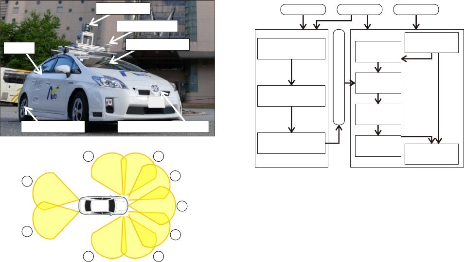
IMU
Rotary Encoder Millimeter-wave Radar
3-D LIDAR
Frontal Camera
GNSS Antenna
(a) Experimental Vehicle
(b) Omni-directional Millimeter-wave Radar
1
2
34
5
9
87
6
Fig. 1. Experimental Vehicle
RTK-GNSS (Real Time Kinematic GNSS) with a post-
processing, providing centimeter positional accuracy. The
key contributions of this paper are as follows.
• Development of both map generation and localization
by modeling uncertainties of MWR, based on error
propagation.
• Quantitative evaluations for accuracy of self-localization
against snowfall, comparing with LIDAR-based method
as baseline.
The rest of this paper is composed as follows. Section II
introduces the experimental vehicle. Section III explains the
2-D map generation using MWR. The proposed localization
method is detailed in Section IV. Section V describes numeri-
cal experiments for urban driving data and evaluation results.
Finally, Section VI concludes with the obtained results and
offers directions for future work.
II. EXPERIMENTAL VEHICLE
Figure 1(a) illustrates our experimental vehicle. The vehi-
cle is equipped with an Applanix POS/LV220 coupled GNSS
and IMU system. It provides position (i.e., latitude, longitude
and altitude) and orientation (pitch, yaw, roll) at 100Hz.
A 3-D LIDAR Velodyne HDL-64E S2 with 64 separate
beams is mounted on a vehicle to take measurements of the
environment. It measures 3-D omnidirectional distance under
a frequency of about 10Hz. Nine MWRs are installed inside
the front and rear bumpers to recognize distant objects, as
shown in Fig. 1(b). It measures distance, angle and relative
velocity for objects at 20Hz. The horizontal field-of-view is
40deg. The number of observations for each MWR is 40.
Map Generation
2D Radar Image Map
RTK-GNSS Radar GNSS/IMU
Moving Object
Tracking
Static Object
Extraction
Mapping &
Updating Radar Map
Realtime Self-Localization
Generating
Obs. Image
Template
Matching
Probability
Updating
Output
Estimated Pose
Dead-
Reckoning
Offset
Updating
Fig. 2. Proposed Localization Method
III. MAP GENERATION
A. Method
A reference map is generated by mapping MWR ob-
servations using the RTK-GNSS with post-processing. The
measuring angle sensing accuracy of 76GHz MWR is gen-
erally not precise compared to LIDAR and 79GHz MWR.
Therefore, it is necessary to consider measurement accuracy
during the mapping procedure. According to the left-side of
Fig. 2, the reference map is generated using the following
processes.
1) Object tracking: estimate static/dynamic bbjects.
2) Static object extraction: remove dynamic objects.
3) Mapping: update a probability of the static objects in
each map pixel.
B. Object Tracking
Object tracking estimates static/dynamic objects us-
ing MWR observations. The interactive multiple model
(IMM) [11] is adopted to integrate multiple types of motions
to estimate position, velocity, and acceleration for the object.
Constant acceleration, constant velocity, and stop models
are defined as motion models. The state variable, x
mwr
is
defined in Eq. (1).
x
mwr
= [p
x
, p
y
, v
x
, v
y
, a
x
, a
y
]
T
(1)
w
mwr
= [w
˙p
x
, w
˙p
y
, w
˙a
x
, w
˙a
y
]
T
(2)
where, p
x
and p
y
are object position in global coordinates
of the Universal Transverse Mercator (UTM) [12]. v
x
, a
x
,
v
y
, and a
y
are velocity and acceleration for the x and y
coordinates, respectively. w
mwr
is a process noise vector for
corresponding variables. For example, a state equation of the
independent constant acceleration model can be formulated
972
of 7
50墨值下载
【版权声明】本文为墨天轮用户原创内容,转载时必须标注文档的来源(墨天轮),文档链接,文档作者等基本信息,否则作者和墨天轮有权追究责任。如果您发现墨天轮中有涉嫌抄袭或者侵权的内容,欢迎发送邮件至:contact@modb.pro进行举报,并提供相关证据,一经查实,墨天轮将立刻删除相关内容。
下载排行榜

评论