


Cabling the Interconnect and Storage for Oracle Database Appliance X9-2-HA.pdf
免费下载
1
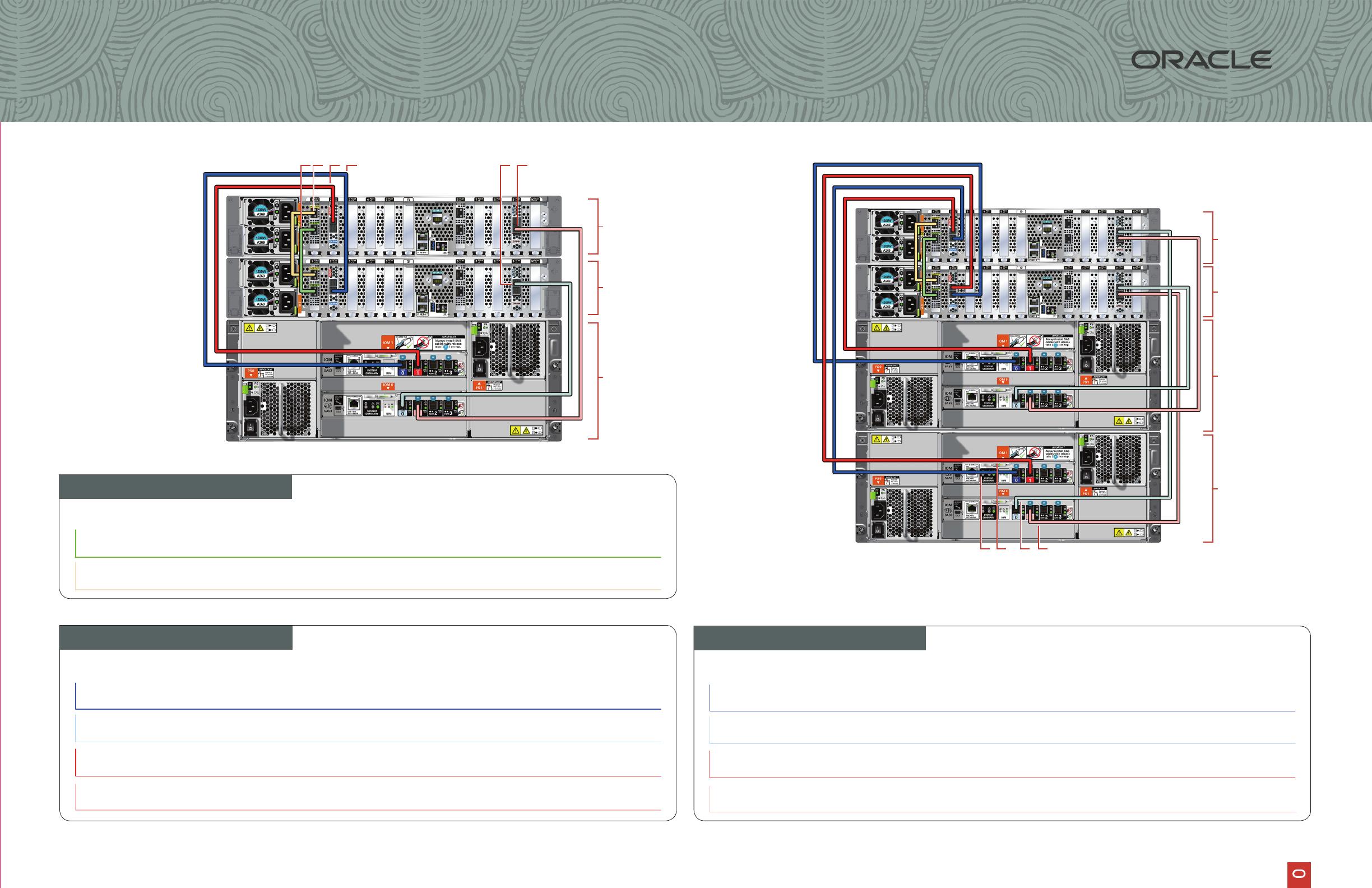
3. Connect dark blue SAS cable Connect into dark blue port
(SAS0) in PCIe slot 2 in Node0
Connect into dark blue port in
top IO Module (PORT 0)
4. Connect light blue SAS cable
Connect into light blue port
(SAS1) in PCIe slot 9 in Node0
Connect into light blue port in
5. Connect dark red SAS cable
Connect into dark red port
(SAS1) in PCIe slot 2 in Node1
Connect into dark red port in
top IO Module (PORT 1)
6. Connect light red SAS cable
Connect into light red port
(SAS0) in PCIe slot 9 in Node1
Connect into light red port in
Purpose
Start - Compute Nodes End - Storage Shelf
Purpose Start - Compute Node0 End - Compute Node1
7. Connect dark blue SAS cable Connect into dark blue port
(SAS0) in PCIe slot 2 in Node1
Connect into dark blue port in
top IO Module (PORT 0)
8. Connect light blue SAS cable
Connect into light blue port
(SAS1) in PCIe slot 9 in Node1
Connect into light blue port in
9. Connect dark red SAS cable
Connect into dark red port
(SAS1) in PCIe slot 2 in Node0
Connect into dark red port in
top IO Module (PORT 1)
10. Connect light red SAS cable
Connect into light red port
(SAS0) in PCIe slot 9 in Node0
Connect into light red port in
Purpose Start - Compute Nodes End - Expansion Shelf
Storage Shelf
Storage Expansion Shelf
Network
1
1. Connect green SFP28 cable
Connect into green port (PORT 2) in
PCIe slot 1
Connect into green port (PORT 2) in
PCIe slot 1
2. Connect yellow SFP28 cable
Connect into yellow port (PORT 1) in
PCIe slot 1
Connect into yellow port (PORT 1) in
PCIe slot 1
Node1
Node0
Storage
Shelf
351 2 64
Storage
Expansion
Shelf
Node1
Node0
Storage
Shelf
8 1097
Connect optional storage
expansion shelf to Oracle
Database Appliance X9-2-HA.
Note: The following cables are
included as part of the Oracle
Database Appliance shipment.
F42007-01; Mfg no 8209586.
Connect interconnect and
storage to Oracle Database
Appliance X9-2-HA.
Note: The following cables are
included as part of the Oracle
Database Appliance shipment.
Database Appliance
Cabling the Interconnect and Storage
for Oracle Database Appliance X9-2-HA

Important:
Follow the instructions on Page 1
and interconnect before proceeding.
On both nodes:
A Plug in AC power to the storage
shelf and host node power
supplies (1) using the power cables
redundancy, ensure that each
its two
power supplies connected to a
separate AC power source.
B Plug in a network cable to the
Oracle Integrated Lights Out
Manager (Oracle ILOM)
C (Optional) On Node0 only,
connect peripheral to USB (3).
D Plug in network cables to the
public network ports (4).
(Port connections can vary
depending on the option ordered).
1
3
Refer to the Oracle Database Appliance Deployment and User’s Guide
To get started with your appliance, refer to the Oracle Database Appliance Welcome Kit at:
h�p://www.oracle.com/goto/oda/docs
2
Start Up the Systems
Connect power to the power supply.
A Power on the storage shelf and optional storage expansion shelf using the ON/OFF switch on each power
B
C
7
6 5
1 4 12 3
Node1
Node0
Storage
Shelf
3
4
12 13 14 15
1 2 5 6 7 8 9 10 11 17 18 19 20
16
Node
Server Back Panel Components, Connectors, and Indicators
2
1
Power Supply (PS) 1 with fan module
2
3
Power Supply (PS) 0 with fan module
4
5
Callout Description
11
12
13
14
USB 3.0 connector
18
19
20
15
16
17
9
7
6
8
For more information about deployment, go to:
Database Appliance
Setup for Oracle Database Appliance X9-2-HA
10
Not used
of 2
免费下载
【版权声明】本文为墨天轮用户原创内容,转载时必须标注文档的来源(墨天轮),文档链接,文档作者等基本信息,否则作者和墨天轮有权追究责任。如果您发现墨天轮中有涉嫌抄袭或者侵权的内容,欢迎发送邮件至:contact@modb.pro进行举报,并提供相关证据,一经查实,墨天轮将立刻删除相关内容。
下载排行榜

评论